Circuitry
The circuit diagram shown below is the one I designed for my team in my Senior Design project. The circuit was designed to power two UV LEDs for water purification as well as include other useful features. For more context about the purpose of this circuit see: Mechanical Engineering Senior Design Project
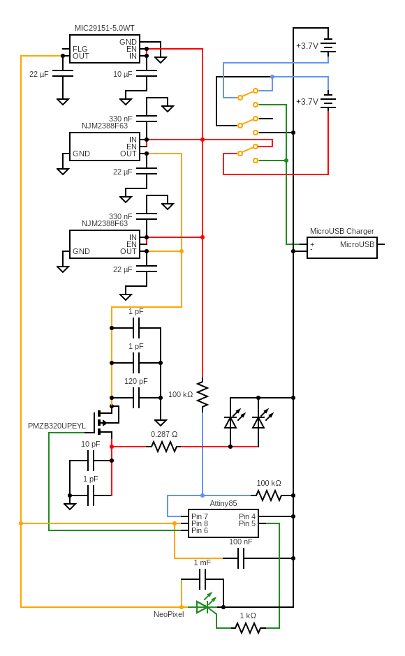
The first goal of the circuitry was that it would be designed to create an effective purification system using the chosen UV LEDs that could be powered for a long amount of time with rechargeable batteries. When choosing 850 mAh 3.7V LiPo Batteries for their compact size, rechargeability, and ability to provide charge for an adequate amount of time, I knew that the UV LEDs would require two batteries connected in series to provide enough voltage to the UV LEDs. The issue was that the SparkFun Micro-USB 3.7V LiPo Charger PCB that was needed to charge the batteries could only provide enough voltage to charge one battery. The solution was to switch the connection between the two batteries from series to parallel for charging, so that the charger could provide enough voltage to charge both batteries at once. This was done using three two-pole-double-throw (2PDT) switches as shown in the top right of the circuit diagram. In the current configuration shown, the two batteries are connected in series to power the UV LEDs and they are disconnected from the Micro-USB Charger. When all three switches are flipped, the circuit connects the two batteries in parallel to the Micro-USB Charger and disconnects them from the rest of the circuit.
Next the goal was to provide a constant voltage and current to the UV LEDs because even though the LiPo batteries were labeled as 3.7V batteries, they did not provide a constant output voltage over their discharge. 3.7V was their nominal voltage rating, however from full charge to low charge, the output voltage would range from 4V to 3.36V, meaning when connected in series, it would range from 8V to 6.72V. The voltage needed for each UV LED was 5.8V, but there would be about a .3V drop over the MOSFET and about a .2V drop over the 0.287 Ohm Resistor, meaning we needed a constant 6.3V before those components. Each UV LED also required 350 mA of current, so two connected in parallel would require 700 mA. This meant a 6.3V regulator after the batteries that could have 700 mA of current passing through it was needed. Unfortunately, no 6.3V regulators that could regulate a voltage as low as 6.72V to 6.3V could handle 700 mA. Instead, two 6.3V regulators (NJM2388F63) that could each individually handle 500 mA were connected in parallel so that a total of 1000 mA could pass through if needed.
Next a visual indication of battery life was needed for the user to understand if the batteries were charged or not and if purification was taking place. At the same time as the batteries being connected in series by the three switches, a microcontroller (Attiny85) would be powered and would read the battery voltage through one of its analog read pins and determine what percentage of charge the battery had left. This first required that the battery output voltage associated with each percentage of charge left was determined so the microcontroller could read a voltage and understand how much battery life was left. This was done using a Sparkfun LiPo fuel gauge circuit that read the battery output voltage and its corresponding State of Charge. From these results, it was found that a voltage of 3.72V corresponded to a battery charge level of 60%, a voltage of 3.41V corresponded to 30% charge, and a voltage of 3.36V corresponded to 17% charge. With this information the microcontroller was programmed to switch the color of a digitally programmable RGB LED (Adafruit NeoPixel). A voltage divider split the combine voltage of the two batteries in series before it was provided to the analog read pin of the microcontroller so the microcontroller would associate half of the total circuit voltage with the individual voltage of each battery. When the microcontroller read 3.72V or greater, the NeoPixel was set to Green, when it read less than that but greater than 3.41V, the color was set to Yellow, when it read less than 3.41V and greater than 3.36V, the color was set to Red, and when it read less than 3.36V, the NeoPixel was turned off. The microcontroller also needed a constant voltage of 5V so it could accurately read the input voltage from the analog pin, so a 5V voltage regulator (MIC29151-5.0WT) was added between the batteries and the microcontroller.
The final consideration was circuit shutoff at low battery. LiPo batteries are sensitive to being overcharged or fully discharged as it can damage them or reduce their battery life. The Micro-USB Charger already had a built-in safeguard for making sure it would not overcharge the LiPo batteries, and each LiPo battery also had its own safeguard PCB built in to prevent overcharging and over-discharging, but it was still necessary that the circuit would not attempt to drain more of the battery at low capacity and not properly purify any water passing through. In order to not pull current to the UV LEDs at low battery when the circuit was switched on (the three switches are flipped so the batteries are connected in series and the charger is disconnected), a P-Channel MOSFET (PMZB320UPEYL) was used to cut off current to the UV LEDs. The MOSFET was placed after the 6.3V regulators and before the UV LEDs and the Gate pin was powered by the Attiny85. When the Attiny85 recognized that the battery life was low (the analog read pin read less than 3.36V), the power to the Gate pin of the MOSFET was cut, stopping current from flowing through the Source and Drain pins of the MOSFET, effectively cutting power to the UV LEDs. This meant the batteries would not need to power the UV LEDs anymore. The batteries would still need to provide current to the Attiny85 at low battery to continue reading the battery voltage, but high resistor values were chosen for powering the Attiny85 and in the voltage divider so that the amount of power needed to control the microcontroller and read battery voltage was extremely small and would drain the battery very slowly before the safeguard PCB built into the batteries would fully shut off the batteries. The microcontroller is also programmed to shut off the NeoPixel and disconnect the UV LEDs after 2 minutes of the circuit being left on under the assumption that the user turned the circuit on and forgot to turn it back off. In order to begin purification again the user needs to flip the circuit off and back on. It is important to note that the user is responsible for understanding that the purification is not taking place as soon as the RGB LED turns off.
Some other details about the circuit are that each of the three 2PDT switches used are magnetic reed switches (MDRR-DT-10-15-F) so that the magnet inside the mouthpiece of the waterbottle lid would actuate the switches with the position of being flipped up for drinking or down for not drinking. This means the mouthpiece effectively acts as the switch for the entire circuit, switching it from “Charging Mode” when the mouthpiece is flipped down to “Purification Mode” when the mouthpiece is flipped up for drinking. All capacitors in the circuit around the voltage regulators, MOSFET, NeoPixel, and Attiny85 are chosen from the recommended capacitance values of their datasheets and spec’d to the voltage at their respective locations.